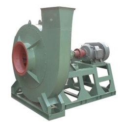
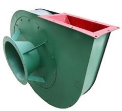
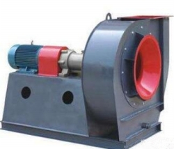
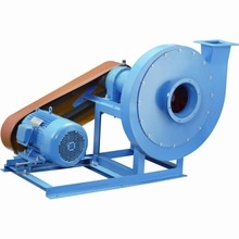
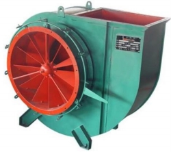
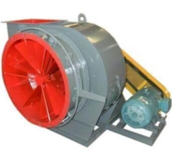
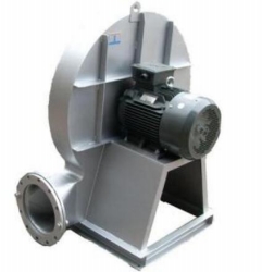
G5-51, Y5-51 Series boiler centrifugal ventilator fan
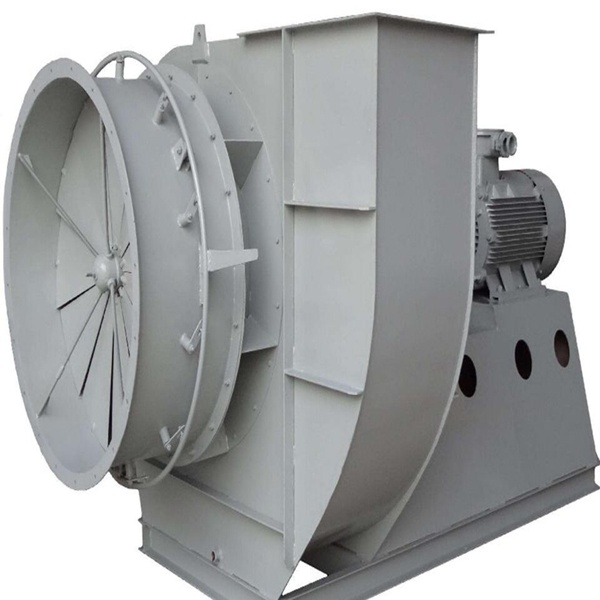
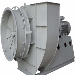
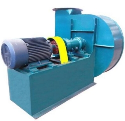
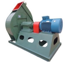
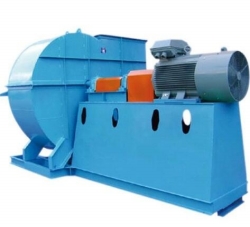
G5-51, Y5-51 NO.8-29.5D boiler centrifugal fan
1. G5-51TY5-51 type boiler draft fan, which is suitable for the draft air system of 2o 670t / h steam boiler in thermal power plant, and also meets the requirements of the performance parameters of high pressure head of fluidized bed boiler. The series fan can also be used for dust removal. Mine ventilation and general ventilation system.
The air blower is transported by air, and the exhaust gas conveyed by the draught fan is a gas containing impurities or particles. When the depth of impurities is less than 200mg/m3, it can be used for more than 4 years. If the impurity is large, it can also be used, but the service life will be shortened. The maximum temperature of the sending and draught fan should not exceed 250 degrees.
2, form
1) draft fan, inducer is made into single suction form. Machine No. 8, 29.5, 20 machine numbers, 40 specifications.
2) each fan can be rotated left or right.
3) the outlet position of the fan is expressed in the angle of the outlet of the machine shell.
4) the drive mode of fan is D type (that is cantilever structure), the connection of motor and fan adopts elastic coupling and direct transmission.
5) the full name of the product is as follows:
G5-51-1 18D 90 degrees right
Y5-51-1 18 D 0 left
Among them, the pressure coefficient of 10 times the pressure coefficient of 10 times that of the boiler blower and the boiler induced fan is the highest efficiency point, respectively. The specific rotational speed is 1 for the first design, and the impeller diameter is 1800mmm.
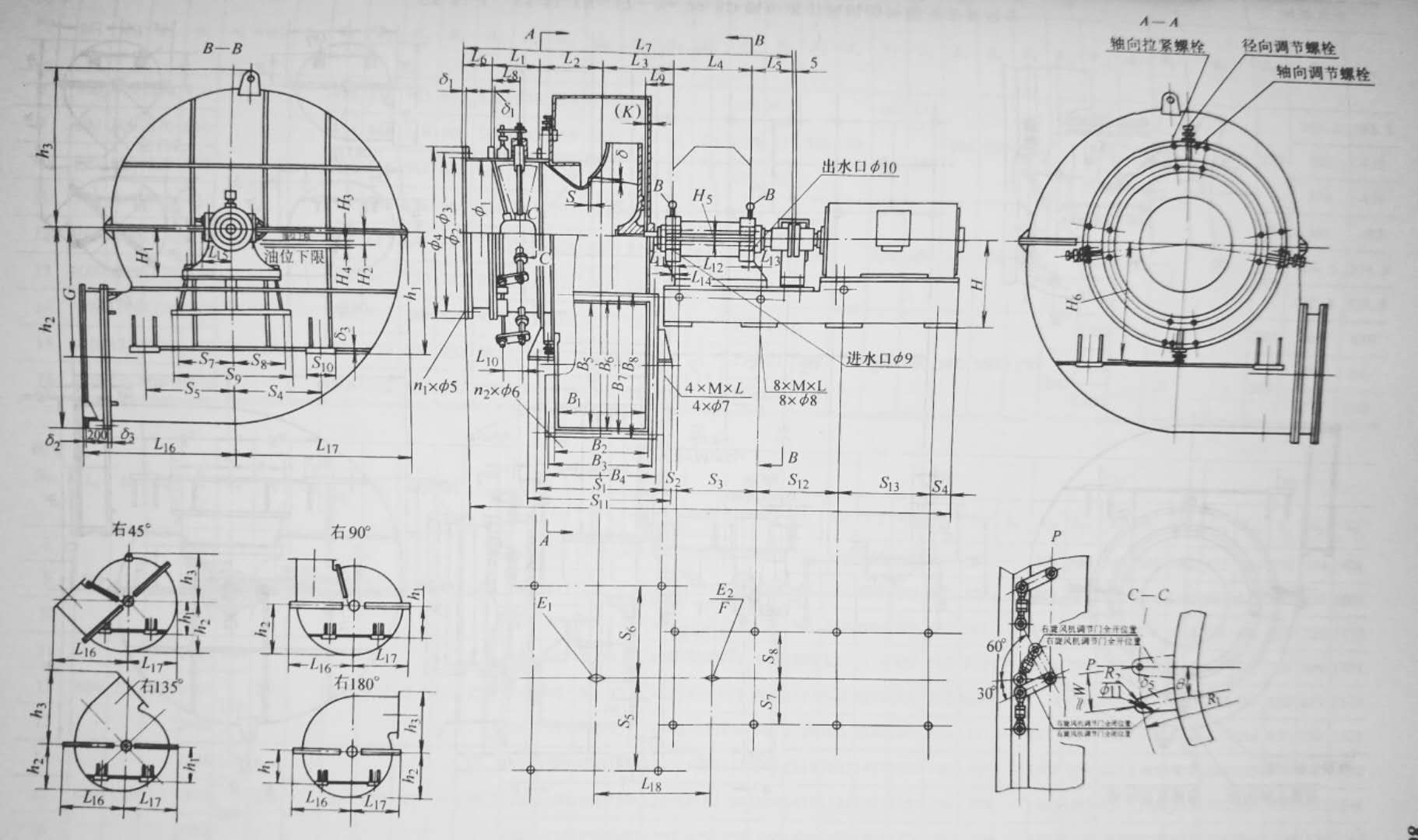
3. Structural characteristics
1) this series of fans adopts advanced technical achievements such as high strength wear resistant impeller, oil leakage proof bearing box, joint axial adjusting door and so on.
2) the wide range of efficient working conditions, the close arrangement of the fan number, and the easy selection of the efficient working conditions.
3) adopt adjustable air inlet. That is, adjust the axial and radial clearance between the inlet and impeller when the fan is installed.
4) High strength wear-resistant impeller. The impeller adopts backward veneer blade to reduce airflow impact, has good stability, the motor is not easy to overload, and greatly prolongs the service life of fan. The fan has high pressure coefficient, low cycle velocity and low noise, so it has good practicability.
5) Oil leakage proof bearing box. The oil from the high speed rotating bearing is thrown into the inner wall of the bearing tank by lap ring, and the semi-open aluminum oil seal is not only convenient for repair and prevention of friction accidents, Part of the thin oil can be cut back to the oil tank by increasing the resistance along the axial direction; the outer pressure plate is to block a small amount of thin oil; the upper part of the bearing box is equipped with a ventilator to reduce the micro-positive pressure in the bearing box, so as to ensure no oil leakage and good dust-proof performance.
6) Articular axial adjusting door. The guide vane fulcrum of the adjusting door and the regulating rod are provided with joint bearing. There is no "dead" point in the running and regulating process, so the adjustment is flexible and labor-saving, the installation is reliable, and the actuator is not loaded.
7) the fan is a monolithic or split assembly type. The transmission set of the series fans below 16D, the coupling cover, and the motor are assembled on a complete base before the motor leaves the factory; the housing, the inlet and the regulating door are another component, Small fans are assembled into two components while large models are decomposed into multiple components for transport and installation.
8) the fan has cantilever structure, convenient arrangement, direct transmission of motor, uniform transfer of torque, reduction of vibration, and reliable operation of the fan.
9) the fan is easy to install and overhaul. The fan has two parts of the complete base, mechanical and transmission units, the housing has a split or vertical face, especially convenient to disassemble and assemble, the rotor can be lifted vertically, if only to replace the impeller can also be axial disassembly.
4, performance and selection
1) the performance of the fan. The performance of fan to fan flow, total pressure, spindle speed, said shaft power and efficiency. The performance parameter selection and performance curve. The blower performance: t=20 degrees, the atmospheric pressure Pa=101325Pa gas density = 1.2kg/m3 air medium is calculated.
The performance of induced draft fan is calculated according to the gas temperature t = 200 ℃ , atmospheric pressure Pa = 101325Pa , gas density ρ = 0.745 kg / m3 .
The performance in the selection curve and performance table refers to the performance of the regulating blade at full open zero degree. The performance table shall prevail when ordering. The deviation of the total pressure value of the fan performance test is not more than ±5 percent of the design full pressure value.
If the operating conditions of the fan are not in accordance with the above mentioned, the performance shall be converted according to the relevant formula.
The treatment of excess or insufficient flow. In use, excess or insufficient flow occurs for many reasons, if it occurs in the course of use, The main reason is that the resistance in the pipe network is large or small. If the resistance in the pipe network decreases gradually over a long period of time or decreases suddenly in a short period of time, it is mainly due to the blockage of the pipe network.
After the new installation of the fan, the main reasons for the excessive or insufficient flow rate during the formal operation are as follows:
The difference between the actual value of pipe network resistance and the calculated value is too large.
From the general pipe network characteristic equation: P0. KQ 2, the K- resistance coefficient is obtained.
If the actual value K is less than the calculated value K, the flow rate increases, and if the actual value K is greater than the calculated value K, the flow rate decreases.
The total pressure deviation Δ P of the fan itself is not taken into account in the selection. When the actual total pressure of the fan is positive deviation, the flow rate increases, and the flow rate decreases when the fan is negative deviation.
When the fan starts to operate formally after the new installation, or when the flow rate is too large or too small during use, it may be eliminated by one of the following methods:
A, use the opening and closing degree of the adjusting door to adjust the flow rate.
B, using the speed of the fan to adjust the flow.
C, using the replacement of new high or low pressure fan to increase or decrease the flow.
D, change the resistance coefficient K to change the flow.
When the adjusting door is completely open, the flow rate is still too small. At this time, the resistance coefficient of the pipe network can be reduced to increase the flow rate, and the fan with higher fan speed and exchange pressure can also be increased, provided that the speed of the fan is not greater than the maximum speed in the performance table.
Please contact us and get detailed Technical parameters and Drawings.
We could Design and Produce the Marine fan,Industrial Fan,and Other Ventilation Equipment according to your detailed requirement !- Previous Product:Y6-11,Y10-11 Series Boiler Centrifugal induced draft fan
- Next Product:Y5-48 Type Boiler use Centrifugal supply fan